
Turning guide
Turning Insert Geometry Guide: Insert Shape, Cutting Angle & Nose Radius
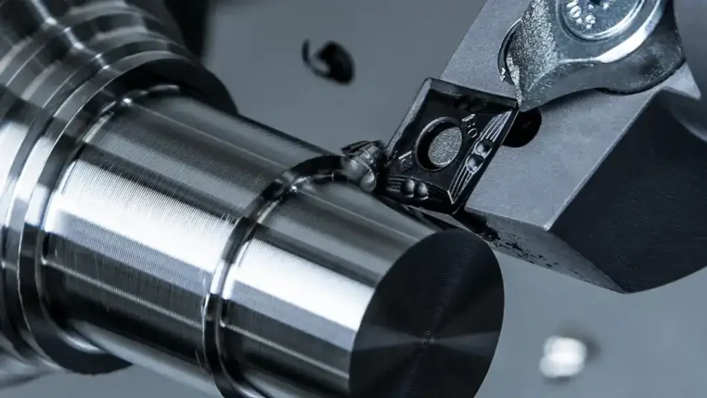
How to Choose the Correct Turning Insert Geometry?
Selecting the correct turning insert geometry is a key factor in achieving stable engagement, predictable tool life, and consistent surface quality in CNC turning. Insert geometry directly influences forces on the tool, chip control, wear behavior, and overall process efficiency. This guide explains how turning insert geometry is defined and how each parameter impacts practical turning tasks.
Why Turning Insert Geometry Matters in CNC Turning
Turning insert geometry determines how the cutting edge engages the workpiece material under specific machining conditions. The geometry of an insert affects cutting force distribution, chip formation, heat generation, and edge strength. An incorrect geometry selection can lead to excessive wear, unstable cutting, poor surface finish, or premature tool failure.
By understanding insert geometry parameters and their functional role, machinists can select the correct turning insert for different operations, materials, and machine conditions while maintaining reliable cutting performance.
Basic Classification of Turning Inserts
Positive vs. Negative Turning Inserts
Negative Indexable Inserts
Negative indexable inserts typically feature a zero or negative clearance angle and double-sided edges. This design provides higher edge strength and allows multiple usable edges per insert, making them suitable for rough and medium machining under higher load conditions.
They are commonly applied where higher feed rates, larger depth of cut, and stable performance on rigid machines are required. The thicker insert cross-section improves resistance to force and wear, particularly in steel and alloy materials.
Positive Indexable Inserts
Positive indexable inserts feature a positive clearance angle, resulting in lower engagement force and smoother material removal. These inserts are usually single-sided and provide sharper edges, making them suitable for finishing work, light machining conditions, and use on less rigid setups.
They are preferred for thin-walled workpieces, smaller equipment, or applications where reduced force and improved surface quality are critical.
Understanding Turning Insert Geometry Parameters (ISO Code Explained)
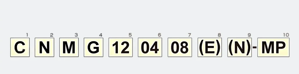
The ISO insert designation system defines the geometry, size, and functional characteristics of a turning insert. Each element of the code corresponds to a specific geometric parameter. The following sections explain these parameters and their role in machining performance. Visual charts and diagrams are commonly used alongside these explanations for clarity.
1. Insert Shape
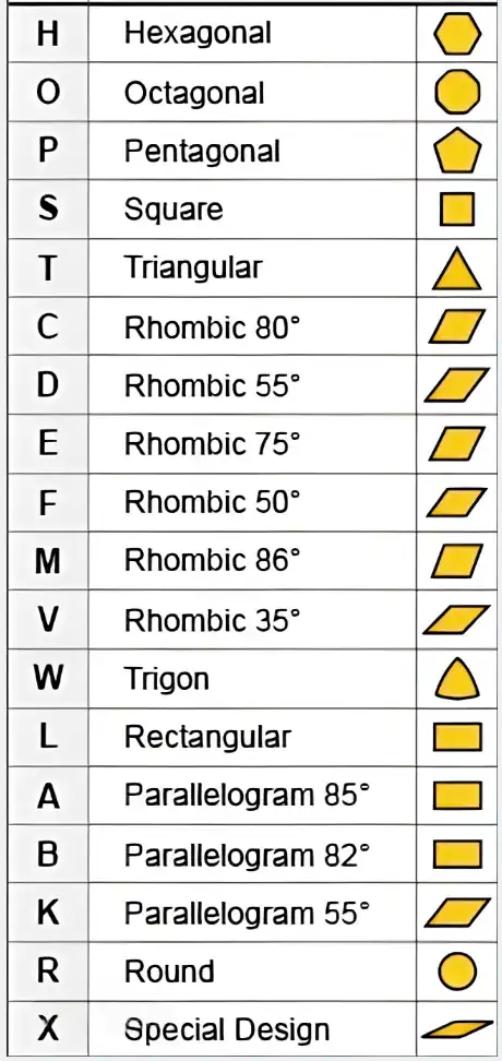
Defines the insert’s overall geometry and included angle, which influence edge strength and accessibility in carbide insert design.
2. Main Cutting Edge Angle
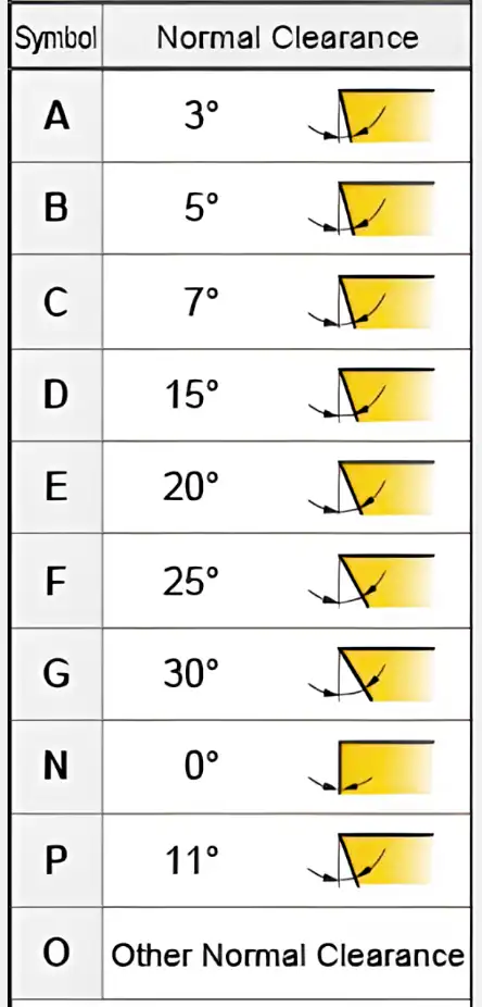
Indicates the orientation of the primary edge relative to the feed direction, affecting load distribution and insert stability.
3. Tolerance
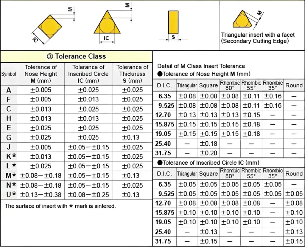
Specifies the dimensional accuracy of the insert, ensuring consistent positioning and repeatable performance across insert grades.
4. Cutting Groove and Clamping Form
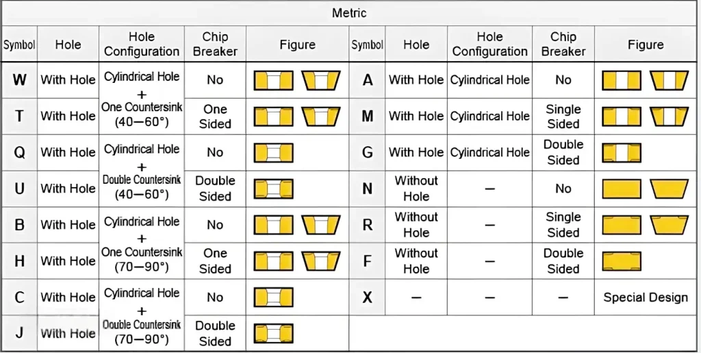
Describes the interface between the insert and toolholder, defining how the insert is supported and secured during machining.
5. Cutting-Edge Length/Diameter IC
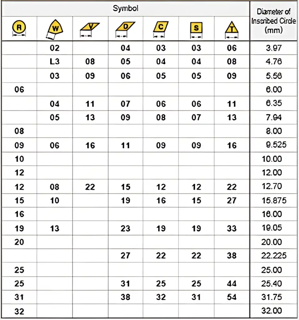
Represents the standardized insert size, used to match insert dimensions with compatible toolholder systems.
6. Thickness
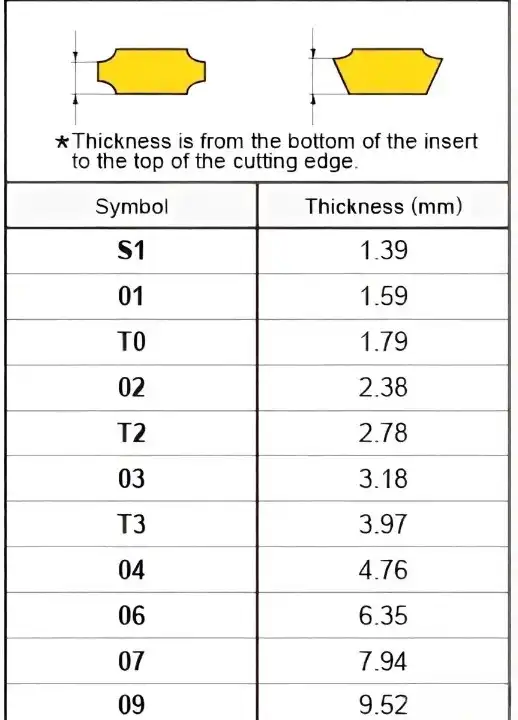
Indicates the insert’s cross-section thickness, which contributes to mechanical strength and resistance to deformation.
7. Nose Radius
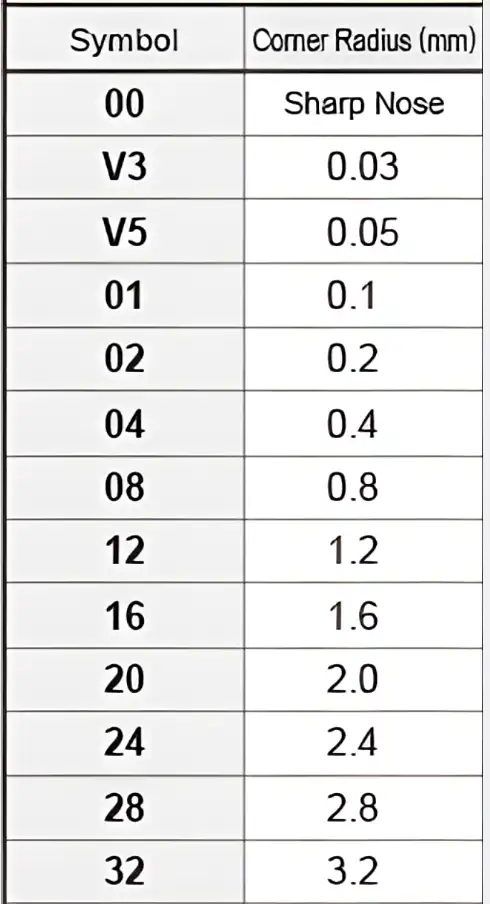
Defines the corner radius at the insert tip, influencing surface quality and stress distribution along the cutting edge.
8. Chip Breaker
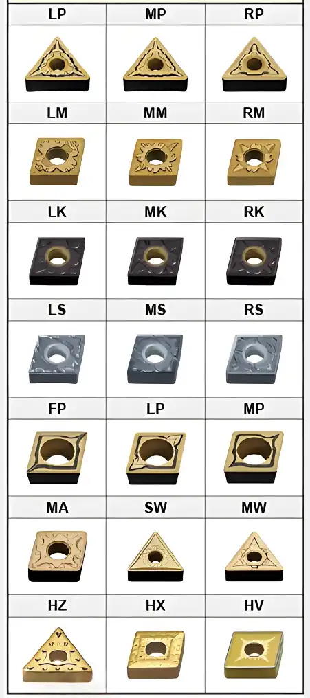
Refers to the formed geometry on the insert surface that guides chip flow and improves control under different feed conditions.
Turning Insert Chipbreaker Types by Machining Application
Chipbreaker geometry is commonly classified according to machining application and cutting conditions. This classification helps match insert performance with specific turning operations.
Roughing Chipbreakers for Heavy Cutting Conditions
Roughing chipbreakers are designed for heavy material removal with higher feed rates and deeper cuts. These chipbreakers provide strong edge support and reliable chip control under demanding working conditions. They are typically applied in roughing tasks where high material removal rate is prioritized.
Medium-Duty Chipbreakers for General Turning Operations
Medium-duty chipbreakers offer a balanced design suitable for a wide range of general turning applications. They provide stable cutting performance, effective chip control, and versatility across different materials and machining parameters. This type is commonly used for semi-finishing operations and general-purpose turning.
Finishing Chipbreakers for Precision Turning
Finishing chipbreakers are optimized for light machining conditions with low feed rates and shallow depths of cut. Their design promotes smooth chip flow, lower force levels, and improved surface quality. These chipbreakers are commonly selected for precision work and final finishing stages.
How to Combine Insert Geometry and Chipbreaker for Optimal Performance
Optimal turning performance is achieved by combining the right insert design with a compatible chipbreaker. Insert shape, edge angle, nose radius, and thickness should be selected in coordination with the chipbreaker type according to the turning process, workpiece material, and overall system rigidity. A well-matched geometry combination helps maintain stable engagement, predictable wear behavior, and consistent surface quality under varying machining conditions.
This geometry-based selection approach is reflected in the design philosophy of FH carbide inserts. Our insert range focuses on practical turning applications, offering commonly used geometries, balanced chipbreaker designs, and compatible grades that support stable performance across different materials and machining setups. By emphasizing reliable specifications, consistent quality, and ready-to-use insert options, FH carbide inserts provide a cost-conscious alternative for shops seeking dependable turning solutions without unnecessary complexity. Learn more about our carbide insert range and application focus on the FH homepage.